Hardware Wiring
This page is used as the on-site wiring checklist for the Marvin Pro system. It covers Tianzhun electric cabinet power, emergency stop, USB drive, communication network, wired headset access, and robot zero-position preparation.
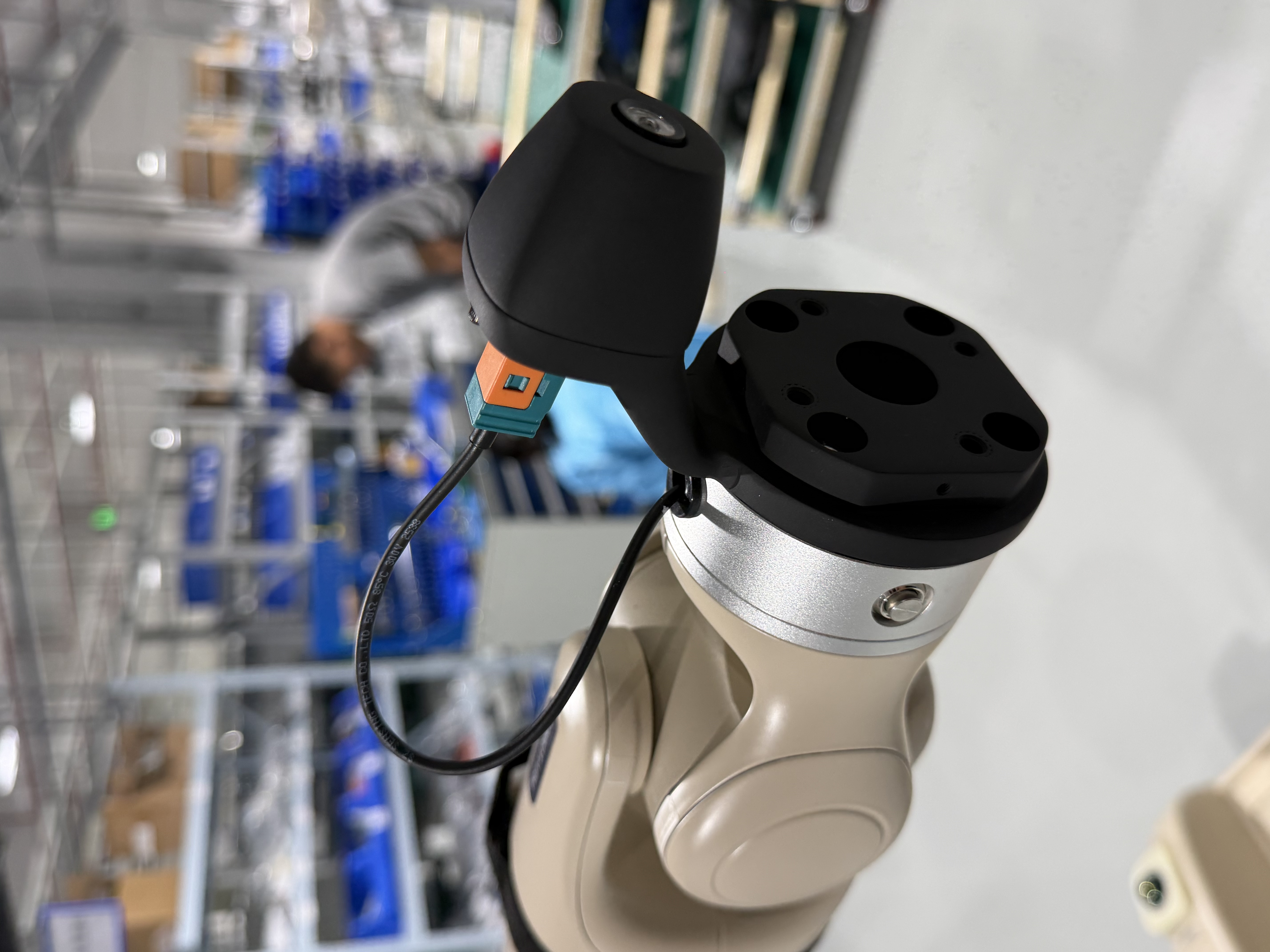
The new version uses the Tianzhun core controller as the main controller. The deserializer board is integrated inside the robot. The Senyun camera is a standard component mounted at the robot arm end, with wiring routed internally through the arm. No separate deserializer wiring is required on site.
Disconnect the main power before wiring. Confirm that all Ethernet cables, power cables, emergency stop cables, and peripheral cables are firmly connected before powering on.
1. Electric Cabinet Power, Emergency Stop, and USB Drive
Complete the following wiring while the main power is disconnected:
- Connect the robot power cable to the electric cabinet
ACINpower interface. The power connector is keyed; insert it in the correct direction. - Connect the emergency stop box to the electric cabinet
E-STOPinterface. Align the red dots before inserting the connector. - Insert the USB drive into the electric cabinet USB port. The USB drive label must be
BAG_STORAGE. - Confirm that the electric cabinet
POWERswitch is off before connecting the network and headset.
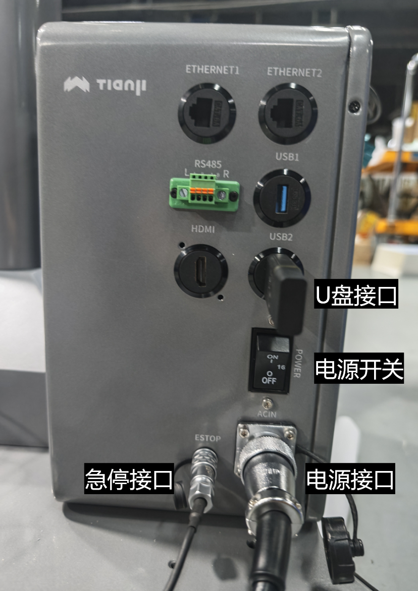
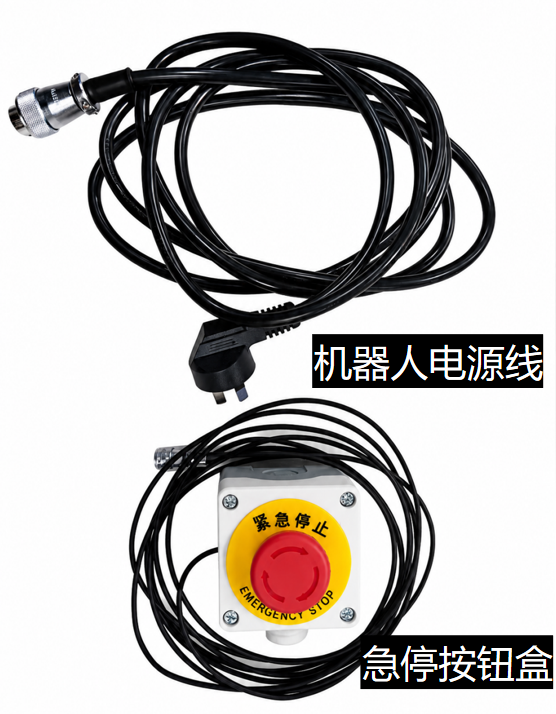
Wiring notes:
- Release the emergency stop button before starting the system.
- The USB drive is used for data recording. Keep the volume label as
BAG_STORAGE. - When using the system for the first time or after replacing the controller, confirm that the robot controller IP is
6.6.7.190. - After the electric cabinet is powered on again, initialize the camera before starting the teleoperation system.
2. First-Unpacking Pose Safety
The robot is delivered with both arms hanging vertically close to the center column. Calling Home directly from this pose can cause a wrist camera to collide with the column.
After completing all wiring, start Robot and click Start Robot. Once the robot is Ready, enable drag mode, manually move both arms to the standard zero pose, and disable drag mode. Only then may you enter Impedance Mode and run Home. See Startup and Debugging: First Unpacking for the complete procedure.
3. Tianzhun Electric Cabinet Interface Check
The Tianzhun core controller integrates main computing, network, USB, power, and emergency stop interfaces. During on-site wiring, connect cables according to the cabinet panel labels and cable labels.
Recommended interface checks:
| Interface / Module | Purpose |
|---|---|
ETHERNET1 / ETHERNET2 | Connects the host PC, headset Ethernet adapter, or on-site network |
USB1 / USB2 | Connects the USB drive, debug devices, or peripherals; the USB drive is used for recorded data |
HDMI | Local display debugging |
ACIN / POWER | Cabinet power input and power switch |
E-STOP | Emergency stop circuit |
DC48V / DC12V indicators | Check 48 V / 12 V power status |
The Senyun camera and deserializer-related wiring are integrated inside the robot. The exposed cable exits from the arm and connects to the camera end. No separate deserializer connection is required on site; only confirm that the camera-end connector and exposed cable are firmly fixed.
4. Network Wiring
The host PC, Tianzhun electric cabinet, and VR headset must be on the same 6.6.7.x subnet.
For wired headset networking, connect a Tianzhun controller to Ethernet port 1 and a Lingjing Thor controller to Ethernet port 2. Both controllers use 6.6.7.100 as the default connection address. Do not interchange the two ports. If the site network was changed, follow the delivered configuration.
| Item | Requirement |
|---|---|
| Host PC | Connect to the electric cabinet by Ethernet; set the network adapter IP to 6.6.7.xxx, for example 6.6.7.165 |
| Tianzhun electric cabinet | Default IP is 6.6.7.100 |
| Robot controller | Default IP is 6.6.7.190 |
| VR headset | Connect to the electric cabinet through an Ethernet-to-Type-C adapter; set the Apex app connection IP to 6.6.7.100 |
Headset connection method:
- Connect one end of the Ethernet cable to port 1 on the robot electric cabinet. For a Lingjing Thor controller, connect it to port 2 instead.
- Connect the other end to the Ethernet-to-Type-C adapter.
- Insert the Type-C connector into the left-side port of the headset.
- Do not enable Wi-Fi on the teleoperation headset. Use the wired network connection first.
Default network parameters:
| Device | Default IP |
|---|---|
| Tianzhun electric cabinet / core controller | 6.6.7.100 |
| Robot controller | 6.6.7.190 |
| Host PC | 6.6.7.xxx, for example 6.6.7.165 |
| Headset Apex app connection IP | 6.6.7.100 |
5. Power-On Check
| Step | Operation | Checkpoint |
|---|---|---|
| 1 | Connect the power cable, emergency stop, and USB drive | Connector direction is correct, emergency stop red dots are aligned, and USB label is BAG_STORAGE |
| 2 | Connect the host PC Ethernet cable | Host PC adapter IP is 6.6.7.xxx |
| 3 | Connect the headset wired network | Headset is connected through the Ethernet-to-Type-C adapter |
| 4 | Turn on the electric cabinet POWER | Wait for the system to boot and check the DC48V / DC12V indicators |
| 5 | Initialize the camera | Run the camera initialization script after the cabinet is powered on again |
| 6 | Check the packing pose | If the arms hang vertically near the column, do not Home directly; after Robot is Ready, enable drag mode, manually move to the standard zero pose, and disable drag mode |
| 7 | Start the teleoperation system | Confirm that the headset or host PC can display the camera view after startup |
If there is no camera view, first check the Senyun camera-end connector, exposed arm cable, camera initialization status, and network signaling address.